

Tools for Good Soldering
Getting good soldering equipment is just as important as acquiring good soldering skills. The tools that you would normally need for basic soldering jobs are:
- Soldering iron / Soldering station
- Solder
- Flux
- De-solder wick / solder sucker
Soldering Iron
A good soldering iron makes soldering easier. When choosing a soldering iron you need to consider:
- Is the iron temperature adjustable?
- What is the temperature range?
- Rated wattage
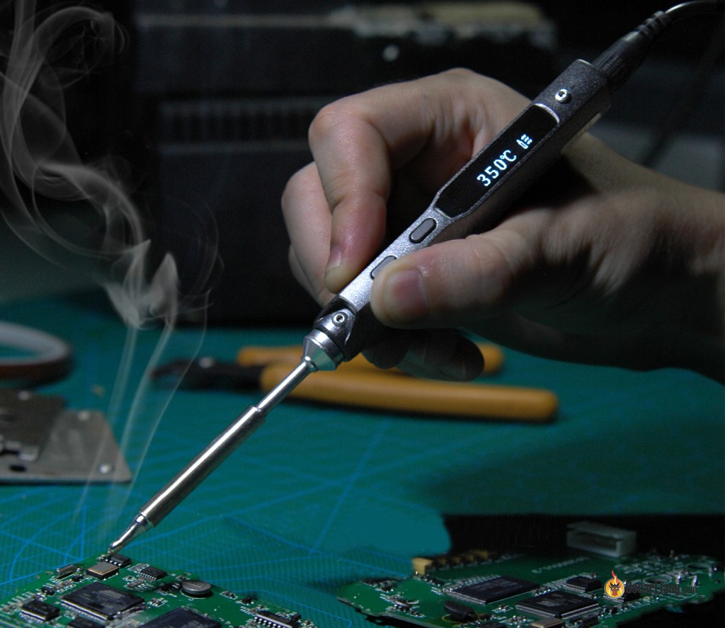
Adjustable temperature control allows you to better handle work of different natures. For delicate soldering like working on small copper pads on the flight controller, you might want to lower the temperate to avoid damage to the board. When soldering large gauge wires or PDB, you will need higher temperature in order to heat up the large volume of metal more quickly.
Having temperature range between 300°C to 400°C is important for our application.
The wattage of a soldering iron usually indicates how much heat it’s able put out. Higher wattage irons are usually better at “heavy duty” soldering, because it’s capable of heating up metal faster without too much temperature drop.
Soldering iron can be fitted with tips of different shapes and sizes. Pointy tips generally are better for precise soldering while larger, wider tips are better at dealing with bigger joints as heat can be transferred to the joint more efficiently. I personally just use a pointy tip for everything related to building and repairing drones.
Solder
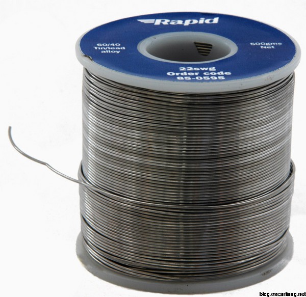
There are different types of solder that are formed of different alloys and elements, each type gives you a different result and designed for different purposes. For electronics hobbyist in general, we highly recommend rosin core 63/37.
If you can’t get your hands on 63/37, 60/40 (60% tin and 40% lead) are also pretty good.
Why use 63/37 solder?
When solder is heated up and melted completely, it will take some time for it to return to solid again if we remove the Iron. We call this period the plastic phase.
You can create bad solder connections if you accidentally move the wires or parts during the plastic phase. Speaking from experience, this can happen often because we normally hold the wires by the fingers during soldering.
63/37 solder has the shortest plastic phase compared to 60/40 and lead-free, which means it becomes solid very quickly after the iron is removed, that’s why 63/37 is useful. It will also help improve soldering quality especially if your soldering skills aren’t perfect.
There really isn’t any downside to 63/37 compared to 60/40, except it’s a tiny bit more expensive, but the price difference is so small it’s negligible.
I also recommend getting Rosin Core solder over Clean core for our application, it’s just easier to work with overall. Especially for large gauge wires which aren’t tin plated, the flux will help with the oxidation tremendously.
Differences between “Rosin Core”, “Clean” and “No Clean”
Rosin core has more flux than clean core in the solder, and it is better for applications where oxidation happens badly.
The downside with rosin core is that it might leave you some “dirty” brown residue at the the solder joints due to the large amount of flux. But you can still manually clean and remove the residue by alcohol.
On the other hand, clean core will give you a much cleaner result right after soldering.
However the residue is not conductive, and doesn’t affect your solder joint performance, so there is nothing to worry about and you can just leave it there.
No Clean is similar to Rosin Core, and it basically means it should be safe to leave the residue on the solder joint.
Solder can come in different diameters: thinner diameter solder wire is preferable which allows for more accurate control of solder flow.
Solder Paste / Flux

Flux is an acid or rosin based compound engaged in the soldering process. It helps clean the solder join as they spread out around the solder joint when heated up.
When metal is heated up, oxidation will build up on the surface and it will prevent heat transferred to the solder joint, you might find solder refuse to flow and stick to the joint and just ball up.
Flux can help remove and prevent oxidation and makes the solder joint accept solder easier than it would be without flux.
Drop a little bit of flux on metal surface before soldering can make it much easier, especially before pre-tinning wires.
If you have a dull and grey soldering joint, that’s usually caused by flux completely burnt out. You can fix that easily by adding a bit more flux to the joint.
De-solder Wick / Solder Sucker


These tools are designed to remove solder off a PCB or wires. You might not need to use this as often as other tools mentioned so far, but it’s handy to have them around.
De-solder Wick acts like a sponge that absorbs melted solder, while Solder Sucker uses a small air vacuum to suck up solder out of a heated joint.
Tip cleaner
When your iron tip starts looking dull, and gathering dirty black stuff, you know you need a tip cleaning. Cleaning your soldering iron tip removes impurity and residual and ensures the best possible result. A cleaned iron tip should look shiny.
A cheap and common cleaner is “heat resistant sponge” that is designed for soldering (make it slightly wet before using). There is also “brass tip cleaner” which lasts longer than sponge, but for us RC hobbyist this might be an overkill for the little amount of soldering we do.
How to Solder – The Tutorial and Exmaples
Soldering is basically joining 2 pieces of metal with melted solder, it’s not too different from gluing. The important thing is to have steady hands, get used to the timing of soldering cooling down and solidify, and learn how to not burn yourself.
Here I will show you how I solder, and give you some common examples you will most likely come across during building and repairing a multirotor.
Before starting to soldering, always add a tiny drop of solder to the tip, this will help heat transferring to the solder joint.
Tinning Wires or Pads
Before you begin joining, always tin (pre-tin) the wires and components first! (except when you are soldering header pins to through holes)
Tinning is basically covering the wire or solder pads with an appropriate amount of solder, this would make joining much easier later on.
You might want to apply some solder paste (flux) first before pre-tinning, especially on wires.


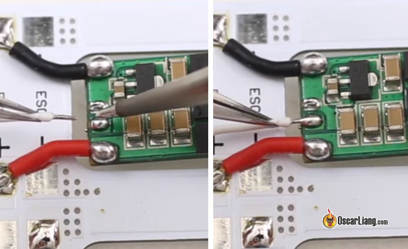
Soldering a wire to a pad
The most common soldering job is soldering a wire to a pad on a PDB or flight controller.
First of all, tin both the wire and the pad. Heat up the pad and melt the solder on it, and bring the wire to the pad quickly. Once the two joins, gently remove your soldering iron, hold the wire for a few seconds until the solder joint cools down and hardens completely.
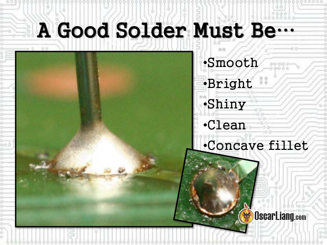
The finish joint should look round, shiny and solid.
Remember not to leave the iron on the pad for too long to avoid overheat and damage to the pad.
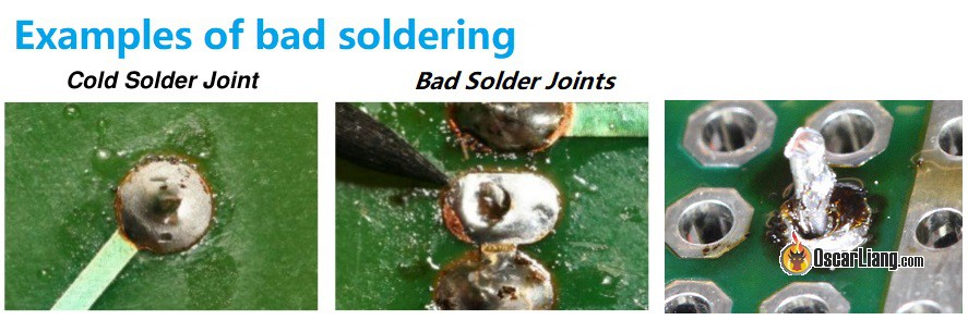
Pro tip: if you let go of the wire too early before the joint completely hardens, or didn’t use enough solder, you might end up with a cold solder joint or just bad solder joint. A cold solder joint looks bumpy and dull, it makes bad contact between the components and is very unreliable. If this happens, or if you are not sure, simply re-do the soldering until you are happy with how it looks.
Soldering thick wires to PDB
If you are soldering a thick wire (e.g. a XT60 pigtail to the PDB), where you make contact with the wire and the pad at the same time, you can try to heat up the wire first, and let the heat pass down to the pad. It usually takes longer to melt the solder on a PDB because of the larger amount of copper in it, this requires a bit more patience and normally higher temperature on the solder iron. Also try not to press too hard on the wire or the wire strands could flattened.

Header Pin to Through-Hole
When soldering a header pin to a through-hole, you shouldn’t pre-tin the components, otherwise it might prevent the header pin passing through the hole.
- Apply solder flux as you see appropriate
- Insert the header pin through the hole
- Heat up both the header pin and the ring on the through hole for a couple of seconds
- Bring the solder to the joint and it should make a solid, shiny, “volcano” like bond

Wire to Through-Hole
There are 2 ways to approach this, you can either treat the through-hole as a solder pad and solder from the top of the board; Or do it like soldering a header pin to a through-hole. It depends on which side of the board you can access more easily.
Soldering wire directly on top of the through-hole:

Insert wire though the hole, and solder from the bottom:

A Wire to Another Wire
It’s easier to use a “solder helping hand” for this job.
For small wires and quick jobs, you could simply solder one wire directly next to the other. You could also twist them before soldering to increase mechanical strength.

When joining 2 larger gauge multi-strand wires together, I normally spread the strands first, and push the 2 wires together head to head, then twist them so they don’t come off easily. Now apply some solder flux, and solder them together.
This way maximizes the contact area of the metal and the benefits are the overall smaller and stronger solder joint. Either way works just fine as long as the joint is solid.

Header Pin on a Pad
You don’t need to tin the header pin nor the solder pad with this job.
- Apply some solder paste on both the pin and pad, and bring the header pin to the pad and hold it there with a Third Hand
- Heat up both the pin and pad for a couple of seconds, and bring solder to the joint
- Remove solder iron and let it cool down
When soldering multiple header pins, I found it gets easier after the first pin, because the whole thing is secured in place firmly by the first pin.

Electrical Wires to XT60 Connector
- Secure the XT60 connector with a helping hand or bench clamp
- Very slightly tin the inside of the XT60 connector. Do not apply too much solder otherwise you might have difficulty inserting the wire into the holes
- Tin the electrical wire, insert the wire into the hole, and heat up both the wire and the connector
- Bring solder to the joint, until the wire is buried in solder
- Remove solder iron, and allow 10+ seconds for it to cool down


Not required but recommended, you can connect the female XT60 connector to a male connector during soldering, this can prevent the gold connectors move around when heated up.

Soldering Temperature
Soldering iron with a higher temperature melts solder faster and might seem to be easier to work with. But overheating solder joints on a PCB is generally not a good idea, therefore using appropriate temperature is very important.
Issues caused by using high temperature when soldering
- Heat can build up and damage components on the board
- Copper pads can fall off due to over-heat
- Oxidation in iron tip and life shortened
Here’s a simple guideline on soldering temperatures I personally follow for good quality 60/40 solder:
- 300 C° (580 °F) – delicate jobs such as joining two small gauge wires together
- 350 C° (660 °F) – signal type of solder joints on a flight controller
- 400 C° (750 °F) – soldering ESC’s power and XT60 pigtail to PDB
For 63/37 solder, you can simply use 10-15C° lower than the above guidelines.
Avoid going over 400C° just to be safe.
If you are having difficulty soldering large connectors or wires, do not blindly increase temperature. You should:
- Check your setup, maybe use a bigger tip which can help transfer heat more efficiently
- Check the quality and type of your solder, try the solder we recommend in this guide if you are not sure
- Use Flux
Soldering Temperature also depends on Power
Temperature can be related to the power of your soldering iron, and the size of the solder joint.
When the iron is making contact with the joint, we can expect the temperature to drop as heat is being dissipated by the copper.
Higher power irons can put out heat faster to the tip and it helps temperature stay the same. For a low power iron in this case, it takes longer for the temperature to recover, so you might want to use a higher temperature to compensate for the dissipated temperature.
1 comment
Betty Hunt
This is really very helpful blog especially the guidelines on soldering temperatures. Actually, I am pursuing IPC training at https://www.solder.net/ and the information is completely helpful during my training.